
Linear rails mounted on aluminium extrusion create a rigid guide. In my workshop, I use this method, yet alignment issues arose, causing backlash and reduced precision. Proper mounting, clearance, and lubrication are essential to achieve smooth, accurate motion. Zero play alignment improve repeatability

Definition and Basic Principles
Linear guide rails are precision‑engineered rail systems that provide a smooth, low‑friction path for linear motion. The core component is a hardened steel rail with a polished profile, typically a trapezoidal or round shape, which mates with a carriage bearing. The carriage contains rollers or balls that roll along the rail surface, translating rotational input from a motor into linear displacement. The fundamental advantage of a linear rail is the separation of load‑bearing and motion‑transmission functions: the rail bears the load, while the carriage transfers motion with minimal backlash.
Key principles governing performance include:
- Load distribution: The rail’s cross‑section and material grade determine how axial, radial, and torsional loads are shared.
- Precision geometry: Tight tolerances in the rail profile and bearing alignment ensure repeatable positioning and reduce deflection.
- Lubrication: Proper greasing or sealed bearings maintain low rolling resistance and extend service life.
- Mounting strategy: Secure attachment to a rigid frame or aluminium extrusion eliminates play and preserves stiffness.
In practice, the rail’s cross‑section is chosen based on the expected load and speed; A trapezoidal rail offers higher stiffness and a larger contact area, while a round rail provides a lower profile and reduced friction; The carriage’s bearing type—roller or ball—affects load capacity and wear characteristics. Proper alignment of the rail and carriage is critical; a misaligned pair can introduce binding, increase wear, and degrade positional accuracy.
When integrated into a machine, linear rails enable high‑speed, high‑accuracy motion, making them indispensable in CNC routers, 3D printers, and robotic arms. Their modularity allows designers to scale systems from small hobbyist setups to industrial production lines. Consistent calibration ensures repeatable positioning across cycles, and regular checks of clearances keep the system within tolerances!!!
Types of Linear Guide Rails
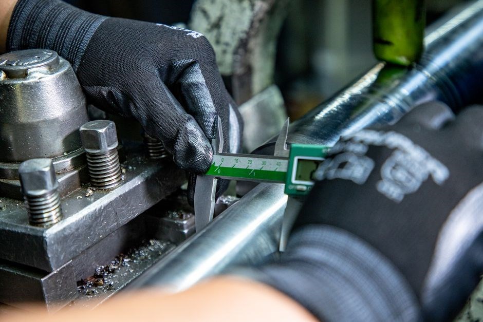
Linear rails vary by profile and bearing type. Carriage rails use a simple trapezoidal rail with a single bearing. Tapered rails feature a stepped profile for higher load capacity. Ball‑bearing rails incorporate rolling elements for reduced friction and higher speed.
Carriage Rail, Tapered, and Ball Bearing Variants
Carriage rails, the most common type, feature a simple trapezoidal rail profile and a single bearing that slides along the rail. They are ideal for light to moderate loads and provide a cost‑effective solution for hobbyist setups. Tapered rails, on the other hand, have a stepped or conical profile that distributes load over a larger surface area, allowing them to handle higher static and dynamic forces. Their design also reduces wear on the bearing surfaces, extending service life. Ball‑bearing rails incorporate rolling elements between the rail and carriage. This configuration dramatically lowers friction, enabling speeds exceeding 50 m/s while maintaining high precision. Ball‑bearing rails are preferred in CNC machines, high‑speed pick‑and‑place robots, and any application where repeatability and speed are critical for precise applications and reduce noise. Each variant offers distinct advantages: carriage rails for simplicity, tapered rails for load capacity, and ball‑bearing rails for speed and accuracy. Selecting the appropriate type depends on the specific application, load requirements, and budget constraints. For high‑precision tasks, a ball‑bearing rail with a low‑friction coating can reduce wear and improve repeatability over time. Conversely, a simple carriage rail may suffice for low‑speed, low‑load hobby projects, saving cost while still delivering acceptable performance, ultimately, the selection hinges on balancing load, speed, precision, and budget, ensuring the linear guide rail meets the demands of the intended application, plus OK

Materials and Construction
Linear guide rails are made from aluminum alloys, stainless steel, or composite laminates. Aluminum offers lightweight solutions for hobbyists. Stainless steel provides corrosion resistance. Composite options combine carbon fiber with polymer cores, reducing vibration and increasing stiffness precision.
Aluminum, Stainless Steel, and Composite Options
Typical rail dimensions span 30–100 mm width and 20–80 mm height, with bearing slots for 12 mm or 16 mm ball bearings. Surface treatments like anodizing, chrome plating, or diamond‑turning improve wear life. Aluminum rails are lighter and cheaper but have lower hardness (≈70 HRC) than stainless steel (≈90 HRC). Composite rails, pricier, offer superior vibration isolation and can be engineered to match load paths, high for precision work.

Load Capacity and Performance Metrics
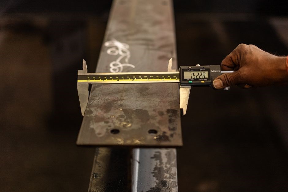
Linear rails handle static loads from 100 kg to 10 kN and dynamic loads up to 1 kN/s, depending on size and bearing type. Precision is measured in µm of runout, with <0;5 µm typical for 30 mm rails. Speed limits range 10–50 m/s, and temperature tolerance up to 120 °C. Ideal for high-speed automation.
Static and Dynamic Load Ratings
Linear guide rails are engineered to support both static and dynamic loads, which are critical parameters for selecting the correct rail for a given application. Static load rating refers to the maximum load that the rail can bear when it is stationary, without any motion. This is typically expressed in kilograms or newtons and is determined by the rail’s cross‑sectional area, material strength, and the geometry of the bearing system. For example, a 30 mm × 30 mm rail made from high‑strength alloy steel can sustain a static load of approximately 1 kN, while a larger 50 mm × 50 mm rail may handle 3 kN or more. Dynamic load rating, on the other hand, describes the maximum load the rail can endure while in motion. It accounts for additional forces such as acceleration, deceleration, and impact, and is usually lower than the static rating because of the added dynamic stresses. Dynamic loads are often expressed in terms of load per unit speed (e.g., N/m) or as a peak dynamic load in newtons. In the dynamic load rating is a decisive factor, as excessive dynamic forces, can lead to increased heat generation, and eventual failure of the bearing elements. Manufacturers provide detailed tables that list static and dynamic load capacities for each rail size and bearing type, allowing engineers to calculate safety margins and select the appropriate rail. When designing a system it is essential to consider both static and dynamic loads as well as the direction of the forces to ensure longterm reliability and performance. Proper load distribution, alignment, and lubrication further enhance the rail’s ability to handle high loads without compromising precision or durability. In practice, engineers often apply a safety factor of 2 to 3, depending on the criticality of the application, to account for unforeseen load spikes and material fatigue. Additionally, the choice of bearing type—ball, roller, or hybrid—impacts the dynamic load rating, with ball bearings typically offering higher dynamic capacities at the expense of increased noise and wear. Regular inspection of the rail surface and timely replacement of worn rollers can extend service life and maintain load performance over time.
Installation and Integration Techniques
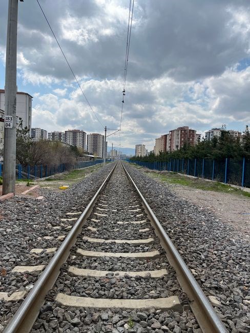
Mount rails on extrusion with precision. Use level tools, secure brackets, and ensure 0.1 mm clearance. Align rails parallel to axis, apply grease, and test motion before final tightening. Proper integration reduces vibration and extends life. Use locking brackets to prevent lateral movement and lock now.
Mounting on Aluminum Extrusion and Frame Fixing
First, select the correct rail size for the extrusion profile. The rail should fit the extrusion’s cross‑section with a tolerance of ±0.05 mm to avoid play. Use a precision level to verify that the rail is perfectly parallel to the extrusion axis. Mount the rail with high‑strength bolts, spacing them 200 mm apart for long runs. Tighten in a star pattern to distribute clamping force evenly. Apply a thin layer of low‑viscosity grease to the rail‑bearing interface before final tightening; this reduces friction and prevents seizing during the first few cycles. When fixing the rail to a frame, use rigid mounting brackets that lock the rail at both ends. The brackets should be bolted to the frame with the same torque specification as the extrusion mounting bolts. Check for any wobble by rotating the rail manually; any movement indicates a mis‑alignment that must be corrected by adjusting the bracket position or tightening the bolts further. After securing the rail, run a test motion at low speed to ensure smooth travel. Inspect the rail for any burrs or debris that could cause binding. If the rail is a ball‑bearing type, verify that the bearing housings are seated correctly; mis‑seated bearings can lead to uneven load distribution. Finally, document the mounting configuration, including bolt patterns and torque values, to facilitate future maintenance or re‑assembly. Proper mounting on aluminium extrusion and secure frame fixing are critical for achieving the high precision and repeatability required in CNC machines, robotics, and 3D printers. Without these steps, the rail system may suffer from backlash, vibration, and premature wear, compromising the entire machine’s performance.

Maintenance and Lubrication Practices
Routine cleaning removes dust that accelerates wear. Apply a thin film of synthetic grease to the rail and carriage every 2000 hours. Inspect for scratches, misalignment, and bearing wear; replace components when wear exceeds 0.05 mm. Document maintenance logs for traceability. Regular checks rails.OK!
Cleaning, Greasing, and Wear Monitoring
- Use a soft brush to remove fine dust before solvent wipe.
- Apply grease with a calibrated dispenser to avoid over‑lubrication.
- Check bearing clearance with feeler gauge; maintain 0.02 mm tolerance.
- Record wear measurements in a spreadsheet for trend analysis.
- Replace worn rail sections before they reach critical deformation.
Regular inspection of rail surfaces for micro‑cracks or pitting is essential, especially in fast or high‑load applications!! Use a magnifying loupe or digital camera to capture images for baseline comparison. When a defect is detected, assess its severity relative to the rail’s design life and decide on corrective action. Documenting each finding ensures traceability and supports warranty claims if needed. Adhering to steps reduces downtime extends rail daily now service life!
Integrating sensor arrays with linear rails enables real‑time monitoring of load, temperature, and vibration. Piezoelectric accelerometers mounted near the carriage can detect micro‑oscillations that precede bearing wear, allowing predictive maintenance. By correlating sensor data with logged wear metrics, engineers can refine lubrication schedules, adjust alignment tolerances, and schedule component replacement before critical thresholds are breached. This proactive approach reduces unscheduled downtime, extends rail life, and improves overall system reliability. Such diagnostics also aid compliance and cost‑effective lifecycle management now.

Applications and Case Studies
Linear guide rails are pivotal in CNC machining, 3D printers, and robotics, providing precision and load capacity. A case study of a 5‑axis CNC shows a 0.02 mm repeatability after upgrade. robotics, rail‑based actuators reduce drift, enhancing accuracy!!! Note:!!
Manufacturing, CNC, Robotics, and 3D Printing
Linear guide rails form the backbone of high‑precision motion systems in modern manufacturing. In CNC machining, they provide the rigid, low‑friction track that allows toolheads to move with sub‑millimeter accuracy over long travel distances. The rails’ smooth surface reduces wear on linear bearings, extending machine life and maintaining calibration. In robotics, linear rails are integrated into actuator assemblies to deliver repeatable positioning for pick‑and‑place, welding, and inspection robots. Their high load capacity and low backlash enable complex multi‑axis coordination, critical for tasks that demand tight tolerances. 3‑D printing machines, especially large‑format printers, use linear rails to support gantry structures, ensuring that extruders follow precise X‑Y‑Z trajectories. The rails’ ability to handle heavy printheads and filament spools while maintaining stiffness is vital for dimensional accuracy and surface finish. Case studies show that upgrading from standard rails to high‑grade, precision‑machined rails can improve print quality by reducing layer shift and enhancing dimensional repeatability. Across all these applications, proper mounting, alignment, and lubrication are essential to unlock the full performance potential of linear guide rails. Linear rails allow quick reconfiguration, enabling users to adapt machines for new products without major redesigns. Their flexibility durability make them indispensable in high‑volume output time; This adaptability reduces downtime and boosts throughput.



Be the first to reply